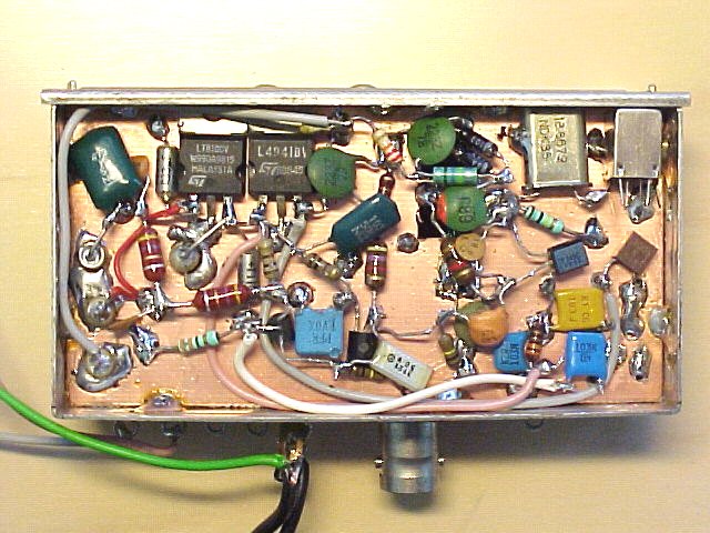
- inside view of the driver ( 89k ) side ( varactors in different configuration than in schematic )
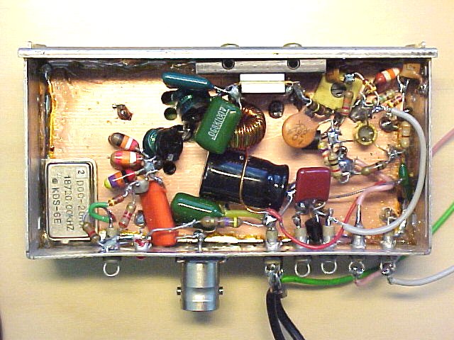
- inside view of the power amplifier/keyer ( 85k ) side with power FET bolted to side wall
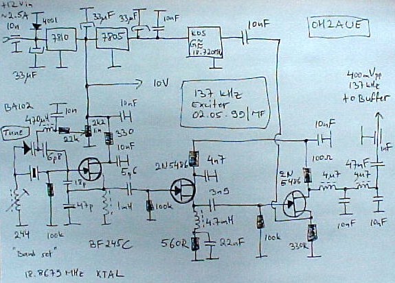
- schematic of the prototype driver ( 68k ) ( fixed frequency oscillator on other side )
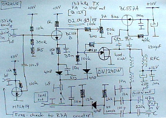
- schematic of the prototype FET power amplifier ( 76k ) ( fixed LO on the right hand side )
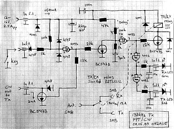
- schematic of the prototype CW/PTT ( 89k ) circuitry used for keying the exciter
- this version had some thermal drift - remedy: desolder the crystal case from the ground plane ;-)
- adding a BPSK modulator for some HeNe LASER AM ( 9k ) sideband modulation experiments