Repair, modification
and alignment work
 Work on OH9VHF and OH9SHF
Beacons (August 2005):
Work on OH9VHF and OH9SHF
Beacons (August 2005):
Return to homepage
- Please Note: many photos on this page are exceptionally
unpacked/resized to maintain good resolution for future reference !!!
OH9SHF:
- an overview photo of the beacons being
run-in after overhaul with OH9SHF (ISEP rack) below and OH9VHF (2 high
Euro rack) on top
- a diagram of the various
interfaces and controls of the two beacons
- 14 years ago, when I built the OH9SHF 1296.945 MHz beacon, I put
in a used fan than now subsequently ran it's bearings out
- so I put in a "new" used fan to see if we could achieve a similar
24/7/365 MTBF as before (this one has an integrated thermostat control)
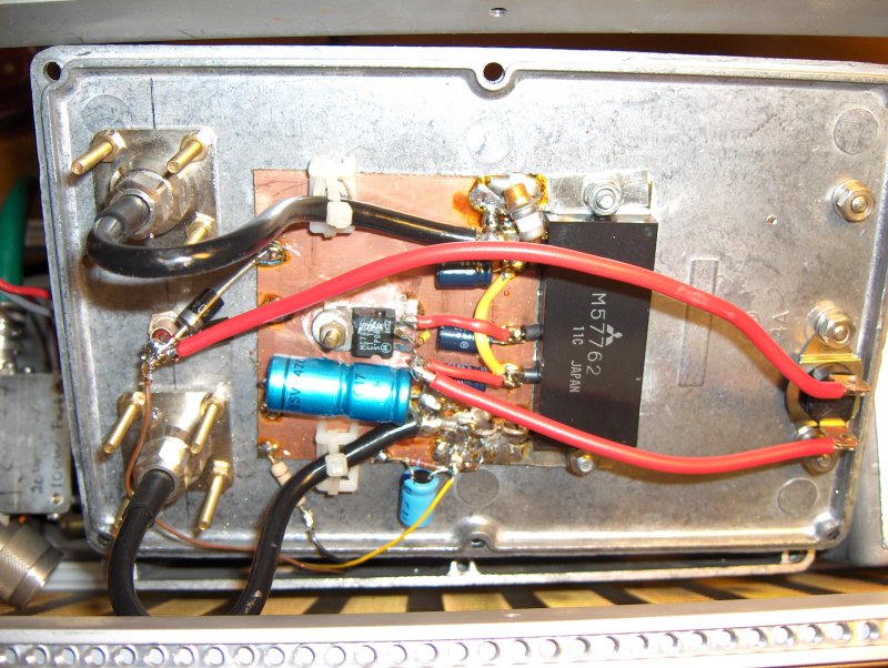
- the output power had also dropped fatally, so a complete lineup
was needed. The output power is now back up to the nominal 12 W
- we really could do with a 100 W class PA, so if you have one you
can part with, please drop me a mail at oh2aue at sral dot fi
- I also now added a 56 degree Centigrade thermal cut-out switch to
disable the PA if cooling is lost
- the beacon had an integrated circulator and 20 W termination
built-in as a protective SWR measure, so it is safe (but bad practise)
to run the beacon without an antenna
- realignment of the 432.315 MHz ovenized exciter was needed and
also the hermetically sealed keying relay was sticky
- upgrading to a semiconductor keying switch was a mere fleeting
thought as I had originally put the relay in a IC holder for easy
maintenance
- so the relay was promptly replaced with a 14 year old spare part
stocked specifically for this purpose :-)
- the 2716 (yes !) EPROM keyer
is housed with the heavily modified DC0DA
exciter board in a diecast aluminium box
- after alignment, the exciter output was back to the nominal output
level of +26 dBm (50 ohm)
- also, the frequency was calibrated during this process and
slightly tuned lower to take aging into account
- realignment of the BGY22 driven BAY96 varactor tripler took place too
supplying the nominal 300 mW RF output on 23 cm - I just love these old
reliable parts ;-)
- photo of the exciter and varactor tripler hooked up for final
output power and spectrum checks
- reference service meter readings for nominal operation: SWR and output RF power
OH9VHF:
- OH9VHF was originally built some 15 years ago by OH2BYW (of the OH2TI group) and indended to actually
become OH6VHF, replacing some really old hardware
- this beacon was upgraded from the older BLY90 45 W PA (down to 38 W
after very careful initial alignment) to a more modern 80 W power
amplifier
- this dual device amplifier can easily do 135 W, is specifed for 80 W
continuous, but as we are amateur, we will settle for 100 W to the
antenna cable...
- I decided to maintain the new amplifier (kindly arranged by OH3BK of
the OH3TR clan) in original
form to ease replacement in case of failure
- unfortunately the original mechanics did not fit the new 2 high
Eurorack, so it had to come apart
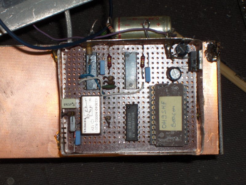
- the keyer, oscillator + oven and the following buffer boards were
removed and appropriate modifications made
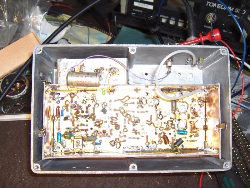
- these three boards I then reintegrated into an old Mobira NMT900
prototype diecast
enclosure (bottom view) that is very easily accessible but is still
extremely RF tight
- here is a topside view
of the module with the 2N6080 driver and 2N4427 predriver at the left,
the ovenized LO in the center and the EPROM keyer to the right
- the 2N6080 has a 4 dB power attenuator at it's output serving two
purposes: damping down the drive to the PA module and protecting the
device from lack of loading
- looking at the bottom (front
panel, without covers) edge, from left to right, you have:
- N(m) RF Output Connector (~300 mW output)
- Remote PA ON/OFF Switch (ON up, OFF down)
- LO Frequency Counter output
- Oven Cold LED (red)
- Key Indicator LED (yellow)
- the power level control remained unimplemented (OM OH2BYW had
originally designed a very stable 0, -10, -20 and -30 dB step concept
into the beacon)
- also, the frequency was badly off after many years of unmanned
7/24/365 service, so the ovenized crystal was tempted back to nominal maintaining
reliable starting
- power to the new beacon design is supplied via the 230 Vac available
and is first switched down to -48 V (the Efore FSR6
was kindly donated by the OH2Z
gang)
- the FSR6 is designed to operate as battery charger also - an option
that may be added later
- the nominal voltage is now set for -48.0 V and the nominal
current is 5.0 A for a solid 100 W RF output from the beacon
- this -48 V is then in turn switched to a highly protected 14.2 V
regulated high current supply
- not everything goes this smoothly and checking the output spectrum
(the original POCSAG BS has an integrated ~cubic meter diplexer) of the
PA was a terrifying experience...
- the first three harmonics were at disastrous levels of -30 dBc, -40
dBc and -55 dBc respectively - somthing definitely needed to be done
- playing around with air dielectric coils and air dielectric trimmers
showed unacceptable losses for this power class
- checking my stocks I decided to test some aluminium-backed Polyflon
substrate and after some coarse calculations, came up with some
approximate numbers
- taking out the Finnish equivalent of an Exacto Knife I came up with this
- then, using some hobby material that is actually steel wire, but
really and truly silver plated (no idea of the thickness though)
donated by OH3UW, turned the coils
- this low-pass filter has excellent characteristics and could cope
with considerably more than 100 W with it's 0.15 dB insertion loss
- of course the rejection band attenuation is very high too, all the
way up to a couple of GHz, but the darn thing just did not fit in the
21 mm left in the rack :-(
- after seriously comtemplating rectangular form (yes - truly !),
I decided to reorientate
the coils, accepting a couple of tradeoffs - power handling and
rejection
- the voltage handling is not so good of course and also the out or
band rejection creaps up due to capasitive coupling over the coils, but
nonetheless...
- ... the three first harmonics are now all at -75 dBc or more - plenty
of headroom to keep any authority happy :-)
- mounting the low pass filter in a PCB material shielded box (without cover),
it was ready for installation onto a 21 mm front panel donated to the
project by OH2LH
- both beacons have now seen some 200 hours of operation on my bench
and are ready for return to Pirttikoski, KP36OI
Spectrum Plots:
- please note, that the graticule plots and actual sweep plots do no
overlay 100 % exactly !
- harmonic components of the
OH9VHF beacon at nominal 100 W output level after the harmonics filter
- calibrated and measured levels of
the OH9VHF output signal (100 W carrier output) harmonics with levels
of approximately -75 dBc
- close-in spectrum of the
OH9VHF carrier (spikes are from the two SMPS switch mode power
supplies), levels approximately -75 dBc
- the OH9SHF beacon 432.315 MHz exciter output spectrum before buffering
and varactor tripling (+26 dBm output @ 50 ohm), 200 MHz/div, 10 dB/div
- OH9SHF RF output after
attenuator (1296.945 MHz, +41 dBm output @ 50 ohm), harmonic level
better than - 70 dBc (other harmonics not meaasurable)
- OH9SHF close-in carrier purity
with 5 MHz span (500 kHz/div) using a linearly regulated laboratory
power supply (an SMPS is used in Pirttikoski)
Created 05.09.2005, updated 04_09_2025