AMSAT-OH designed and constructed the 10 GHz transmitter payload for the Phase 3 D international radio amateur satellite. I have been with this group since almost the very beginning seven years back. I have done loads of prototyping on the microwave and RF parts from IF to antenna. For more information on the basic principle, see the block diagram( 16 kb ). This was designed constructed and installed onto the P3D spacecraft by the AMSAT-OH team, a member group of RATS ( the Radio Amateur Technology Society ).
The redundant power amplifier system includes both a travelling wave tube amplifier, TWTA supplied by AMSAT-DL and a solid state power amplifier, SSPA, designed and build by AMSAT-OH also. See block diagram ( 9 kb ).
Killing 60 Watts of 10 GHz RF without radiating the power everywhere and still presenting a good match requires some pretty hi-tech solutions. What you see here ( 200 k ) is an RF load made from a jam can and some black sement. I wonder why I am all alone in the AMSAT-NA clean room in Orlando, Florida ??? The load was made by KK6TG. The absorbing material is actually carbon impregnated and fiber reinforced concrete. The load absorbed all the RF without any difficulty or overheating. You can see the copper and aluminium tape I used to RF sield the the slot between the can load and the spacecraft outer surface. In the picture you can se me adjusting the load height inside the can with the bolt used to suspend the concrete cone for optimum matching. The return loss achieved was around 30 dB, which is excellent. The directional coupler and powermeter sensor you can see in the foreground.
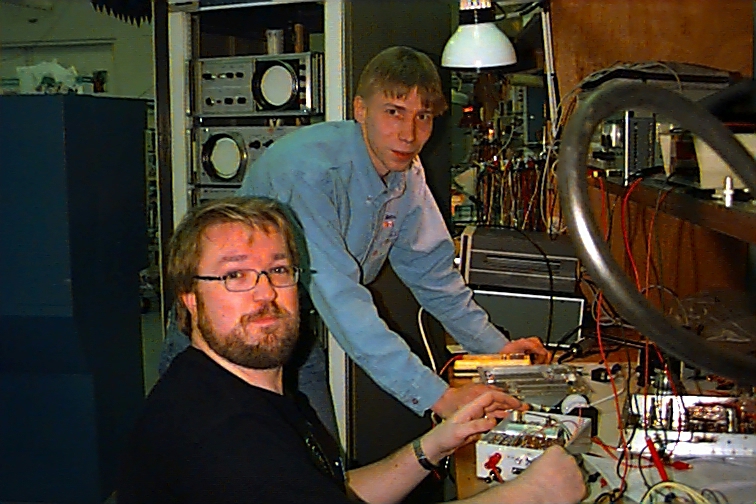
My interface box for controlling the X-band transmitter is receiving an additional ( 200 k ) function on the AMSAT-NA integration lab table. OH2JMS is trying to keep a serious face while seeing what the hi-tech box incorporates...
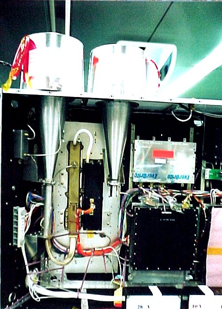
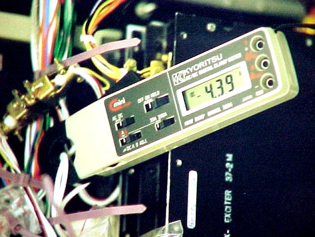
Some more pictures: the SSPA, TWTA and antenna horns ( 88k ) as flight installed on the spacecraft, a closer view of the TWTA ( 65k ), a closup of the current clamp ( 84k ) indicating maximum load on the 28 V bus and the respective output power ( 65 ) of the TWTA ( 59 W !!! ).