| Prototyping
techniques for RF&MW |
6 cm band stuff
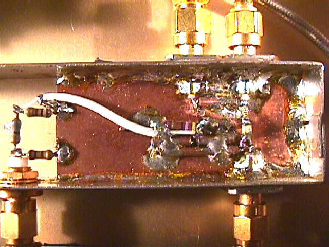 |
Coaxial transmission line can be used
for phase control and even for matching if you can find coax of different
impedances. 25 and 75 ohm line is readily available in addition to the
traditional 50 ohm line. Coax is also available in a wide range of diameters
and the thinner cables can be used at pretty high frequencies in even short
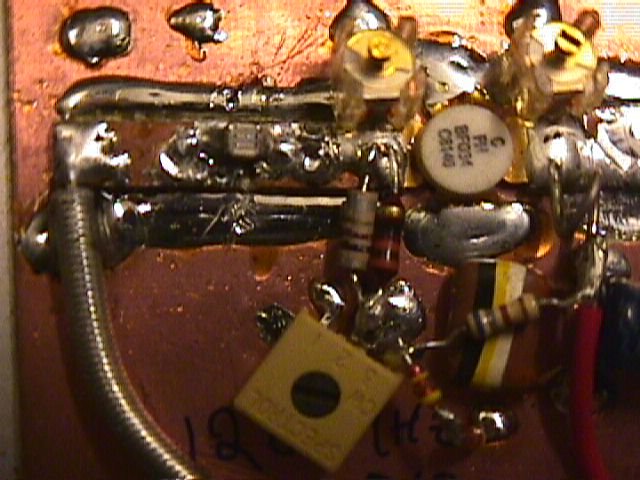
lenghts. In this picture you can see my 6 cm ( 5760 MHz ) pushpull mixer
using a four diode package ( specified to 2 GHz ! ). The conversion loss
is about 7 dB and you can also see a power splitter made using 75 ohm coax
and a 100 ohm resistor ( a Wilkinson divider ). This mixer was intended
as a prototype, but as often happens, it ended up as the final TX mixer
for the 6 cm EME/troposcatter transverter described elsewhere on my homepage.
The discrete 1/4 watt resistor attenuator is the TX path attenuator for
the 144 MHz IF. The mixer uses a 3 dBm LO at half of the final frequency
( a harmonic mixer of sorts ). |
9 cm stuff
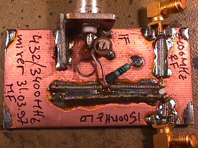
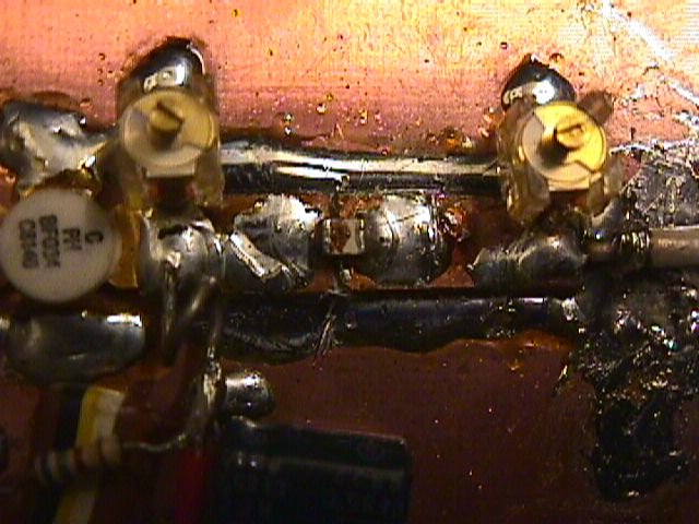
| This is a similar mixer arrangement
for the 9 cm band ( 3400 MHz ). Here the IF is 432 MHz to improve image
and LO rejection with more elementary filtering. This mixer can run with
- 3 dBm of LO at half the final frequency. With + 3 dBm of LO level, the
conversion loss is about 6 dB. This mixer remained a prototype and a GaAs-FET
mixer designed by DB6NT was used for the EME rig described elsewhere on
my homepage. The mixer is very easy to build and I use it for mixing signals
from LO's under work to a more suitable IF for my spectrum analyser and
frequency counter. It also provides nice 3400 MHz SSB and CW signals for
verification of correct operation of other equipment. The mixer diodes
are also a four diode affair forming a ring, but are connected in a pushpull
manner ( two in each direction ). |
 |
13 cm band stuff
 |
This 13 cm ( 2.3 GHz ) mixer was the
first of this type for me to experiment with. The conversion loss is 6.5
dB and the mixer works very well. The mixer diodes are a diode ring of
four specified for 2 GHz operation. This mixer served well in my first
2.3 GHz transverter. I used two mixers, one for the TX and the other for
the RX chain. This mixer is very noncritical at this frequency as the tolerances
are not very tight. The IF for this mixer is 144 MHz out of convenience.
A 432 MHz IF would be better from the technical point of view. The starved
LO level is about - 3 dBm at half the final frequency. This mixer takes
about an hour to make if you have everything handy !!! |
23 cm stuff
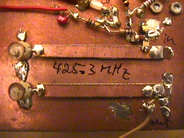
| When prototyping filters and matching
circuitry for frequencies between 300 and 3000 MHz I use double sided fiberglass
or PTFE circuit board laminate that I empirically "cut to size" with a
pair of scissors dedicated to this. Striplines may also be made air dielecric
for lower loss and higher frequencies. The filter striplines are soldered
down directly onto a ground plane circuit board. This ground plane exhibits
excellent RF return and is a very stable environment for this type of circuitry.
In the engineering stage the striplines are soldered from each end only
and when the final dimensions and distances/gaps are determined, the striplines
are soldered down all the way along their length. The 50 ohm tap points
are determined empirically and experimentally. The parasitic parallel element
is very critical to tune due to high impedances. Be careful when tuning
not to miss the very narrow resonant frequency ! The extensive availability
of MMIC circuits makes building a complete LO chain and mixer with preamplifier
possible in a single evening without any predesigning ! |
 |
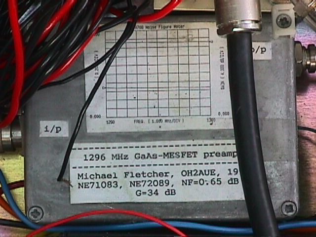 |
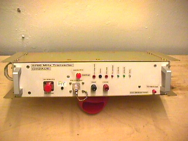
And of course the average good looking
enclosure may keep within all kinds of murky secrets that may have indescribable
appearance, but work like a charm... The innerds of this 0.7 dB max. preamp
for 1.3 GHz is a three stage preamp built into a circuit board enclosure
using the described techniques. The amplifier is stable and exhibits 34
dB of gain. The preamp is used in conjuction with a 60 Watt SSPA based
on four Mitsubishi broadband hybrid amplifiers. The preamp is in a weather
tight double enclosure with an N type connector for input and a less desirable
BNC for the output. The preamp uses two GaAs-FET's and has paved the path
for a similar P-HEMT preamp that has an even lower noise temperature. |
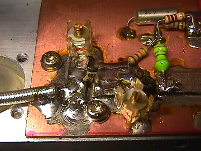
More 23 cm stuff
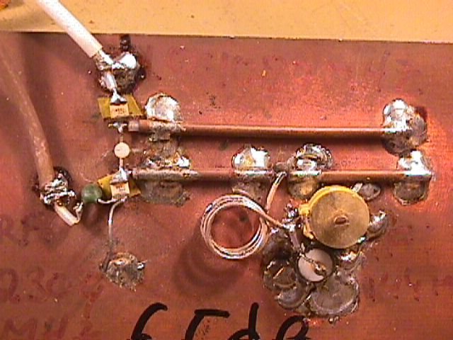
| Here are some low power amplifier
stages constructed using the descibed cut and glue technique. The driver
amplifier uses a BLU98 transistor for 11 dB of gain at 1296 MHz. The image
shows how the input matching has been accomplished. The input goes through
a parallel resonant circuit tuned with a plastic foil trimmer. Bias is
fed via a 1 kohm mass resistor with low series inductance at RF. The resistor
cold end is terminated with a Hi-Q chip capacitor. The DC decoupling capacitor
is part of the matching and there is also a low impedance series stripline
terminated with the tranistor base and a parallel trimmer capacitor. The
input return loss is approx. 15 dB which is adequate for the purpose. |
 |
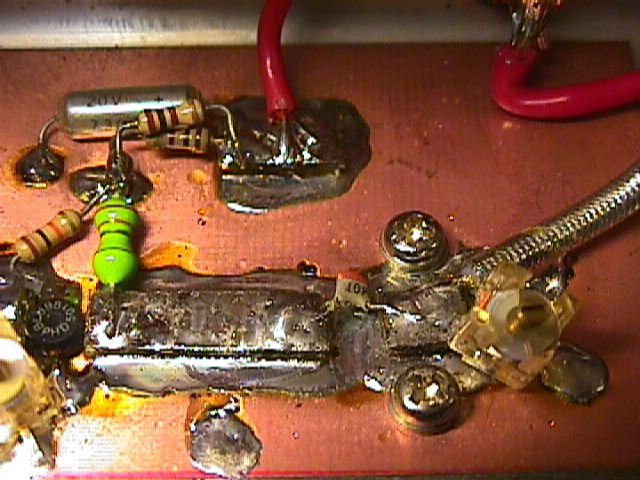 |
The output circuitry consists of a
series transmission line, also of fairly low impedance ( wide stripline
). The DC decoupling capacitor is also part of the matching scheme. This
could also be a trimmer, as is the parallel trimmer. The capacitive voltage
divider would then be easier to tune and the trimmers could be replaced
with fixed value caps ( that is if you can estimate the stray components
accurately enough !!! ). The collector voltage is supplied via an RF choke. |
23 cm 1 W amplifier
| This is a photo of the input matching
found to be useful for the BFQ34 input at 1296 MHz. There is essentially
a low impedance series transmission line terminated with the base and a
parallel trimmer capacitor. The bias is fed via an RF choke with settable
bias current. The base voltage is regulated by a Si diode. the PCB is bolted
down to an aluminium heat sink with thermal compound on the tranistor bolt.
The transistor emitters are soldered directly to the PCB ground plane with
shorting foil to the bottom copper laminate. The foil is wide so as to
exhibit low series RF inductance at 1.3 GHz. |
 |
 |
Matching the output of the BFQ34 at
1296 MHz is very simple too. The output matching is basically a PI-type
circuit with two trimmer capacitors and and a series inductance ( wide
stripline ). The collector voltage is supplied via an RF choke formed by
one turn of thin copper wire terminated with a Hi-Q capacitor for RF bypass.
The output of the amplifier is 1 W with a gain of 7 dB. |
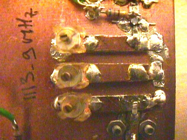
Even for 70 cm !!!
| The only reason why you could not
use this kind of prototyping techniques is the practicality of of dimenstions.
At 70 cm the sizes are still quite reasonable though as you can see from
this stripline filter ( the striplines have not yet been soldered down
properly ). After having found the coax/stripline dimensions, all you need
is a slide rule to determine resonator sizes for etched versions of the
PCB. It will take some practise to guestimate the the edge and stray effects
of the prototypes...but this is all part of the fun !!! |
 |
|