I also had the opportunity to attend the AMSAT-NA Space Symposium in
Vicksburg, Mississippi during my trip to the USA.
Sponsors of my trip to Mississippi and Maryland:
- Anritsu Corporation/Anritsu Nordic
- The Radio Amateur Technology Society
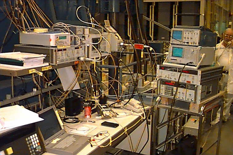
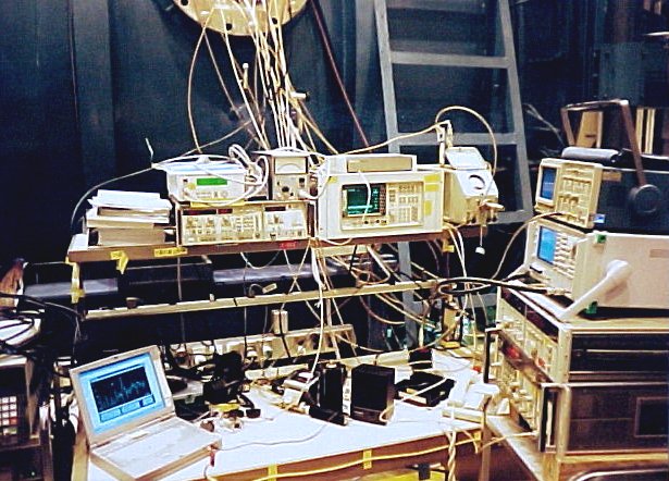
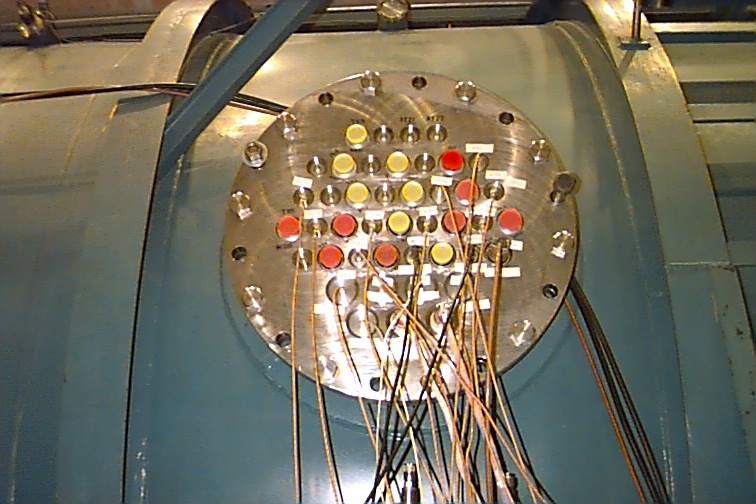
The trip started with my attendance to the three day Space Symposium in Vicksburg, from where I flew up to Baltimore to the Orbital Sciences Corp. facilities in Germantown. The tests took a lot of preparing for at both my end and also by the AMSAT-NA team in Orlando, Florida. All the RF & microwave test equipment was provided by Anritsu, NASA Goddard Spaceflight Center and Orbital Sciences Corp. The range of equipment was very broad covering frequencies of 21 MHz to 24 GHz. There is a lot to test as there are nine receivers and six transmitters onboard the spacecraft ! This is what the test bench ( 226 kb ) looked like and here is another view ( 90k ) of the bench too. The bulkhead ( 171 kb ) was the interface through which all RF & microwave signals were routed along with the HV for the Electronic Propulsion Unit and other cabling.
Simultaneously the RUDAK test team were testing their payloads and for
this purpose three ground stations were assembled in the vicinity of the
facility. Two command stations were also assembled by the team to command
and control the satellite during the vacuum tests. One command station
was operated over the umbilical cord and the second was an RF command station.
Rick Leon, KA1RHL, had the brilliant idea of placing a microphone onto the spacecraft
to listen to the different sounds mechanically emanating from the spacecraft
during the thermal vacuum test. The microphone used was a standard Radio Shack
piezoelectric sounder that was taped onto the P3D bus with Kapton tape. The
sounder was equipped with a coax cable that we routed throught he bulkhead with
all the other cabling. The very high impedance microphone was coupled to an
analogue oscilloscope at channel 2 so that the channel 2 buffered output at the
rear could be used to feed my laptop PC. In this way the scope could be used as
a conditioning amplifier. I used an excellent piece of audio analysis software by Richard S. Horn
called gram.exe that can be downloaded from the web at:
http://www.monumental.com/rshorne/gram.html
I managed to record some spectacular sounds that include creaking of the
metalwork under thermal stress, clicking of vacuum relays in the spacecraft
and interesting things like the sound of the momentum wheels being activated.
You could clearly hear the momentum wheels going from steady state ( we are
still in the earths gravity field !!! ) to levitation as the magnetic suspension
fields are actived. You can also hear the steady hiss of the switchmode
power supplies and the control circuitry as it continuously controls the magnetic
fields around the ballbearingless momentum wheels to maintain levitation.
Not to speak of the sounds as the wheels are set to motion and accelerated to
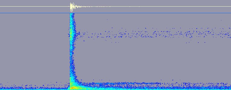
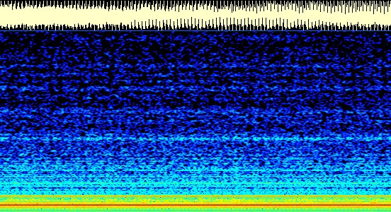
the preset rpm !!! Here you can see what the sound of
levitation ( 34k ) activation looks like and you can also see the hiss of the control
electronics at approx. 4 kHz. The top plot is a time domain "scope" shot of the
event and the bottom is the frequency distribution ( spectrum ) of the event over time.
This is what the activation ( 237k ) actually sounded like...
And this is what it looks ( 94k ) and sounds ( 147k ) like when all three momentum wheels are activated and set and syncronized to 2000 rpm.
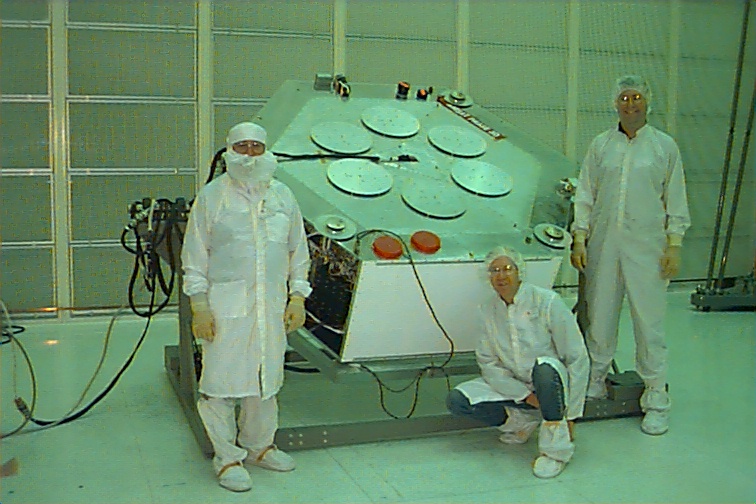
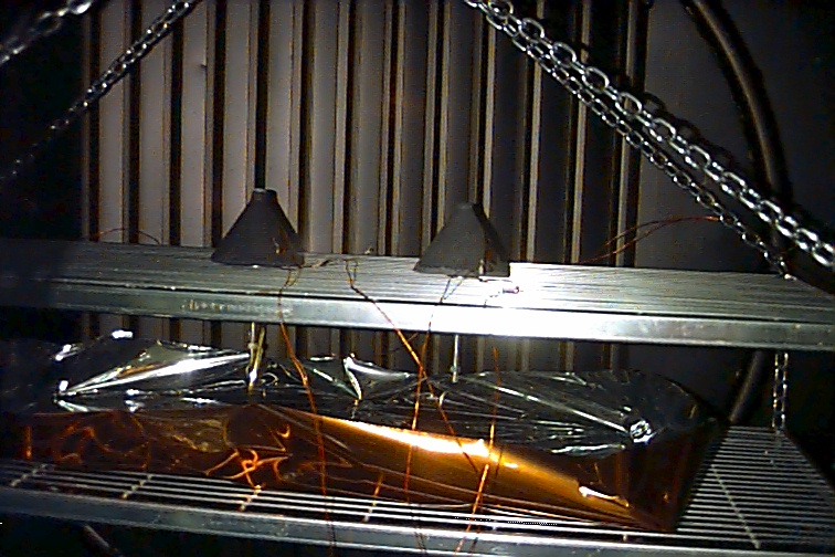
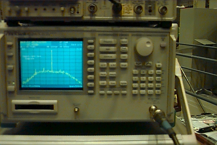
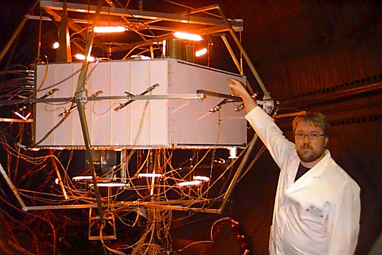
Before actually moving the spacecraft into the vacuum chamber, there was a lot of preparation of P3D to be seen to in the clean room ( 159 kb ), such as installing the 10 and 24 GHz RF loads and the 20 + temperature sensors that are needed to monitor the actual spacecraft internal and external tempreratures during the Thermal Vacuum tests. The equipment was thoroughly tested at temperature extremes of -25 and + 45 degrees C under a vacuum of 10E-6 Torr. The solar panels were kept in a separate vacuum chamber for a few days as were also the concrete loads ( 182 k ) used for dissipating the 10 GHz RF energy of the high power microwave transmitter supplied by our Finnish AMSAT-OH team. This payload was installed last spring and there is more on this elsewhere on my homepage. This equipment is going to be fun to work with very good signal to noise ratios as you can see on the Anritsu 30 GHz Spectrum Analyzer ( 151 kb ) screen. What you are looking at here is the 10 GHz downlink ( 4 kb ) with a solid copy 1.3 GHz signal on the uplink. This is what the downlink looks like with a 5.7 GHz ( 4 kb ) carrier on the uplink ( images without beacons or RUDAK, just the receiver passband ).
The test ran for almost two weeks and the exhausted team was satisfied with the outcome of the Thermal Vacuum tests. The final test of the spacecraft is the Vibration Test and after this we are ready for launch !!!
This time the team consisted of:
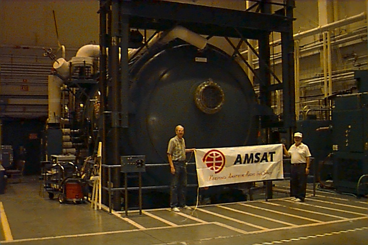
- Me ( 198 kb ) pointing at the X-band transmitter concrete loads
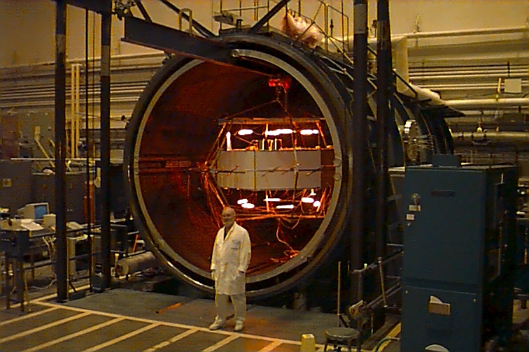
- P3D Integration Lab Manager Lou McFadin, W5DID ( 186 kb ) in from of the Vacuum Test Chamber
- Photo of just some of the group ( 91 kb ) that participated in the testing
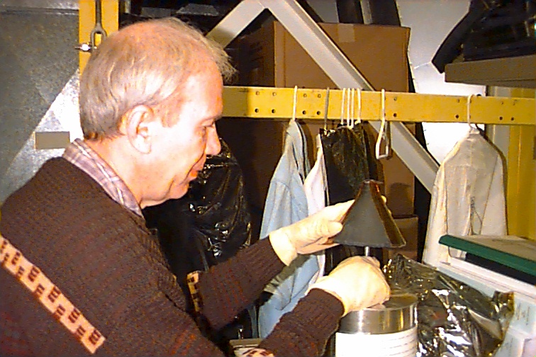
- Chuck Green covering the 10 GHz cement loads ( 185 kb ) with Kapton tape
- Another view of the chamber ( 173 kb ) with Chuck and Lou
We'll be back...
Updated 17.11.1998/Michael Fletcher