- the Motoroal XRF187S/MRF187S has proven to be extremely robust
- amplifier drivers etc. were discarded
- input 90 degree 3dB couplers were exchanged for 1.3 GHz versions, originals appear to be reasonable even at 1.3 GHz
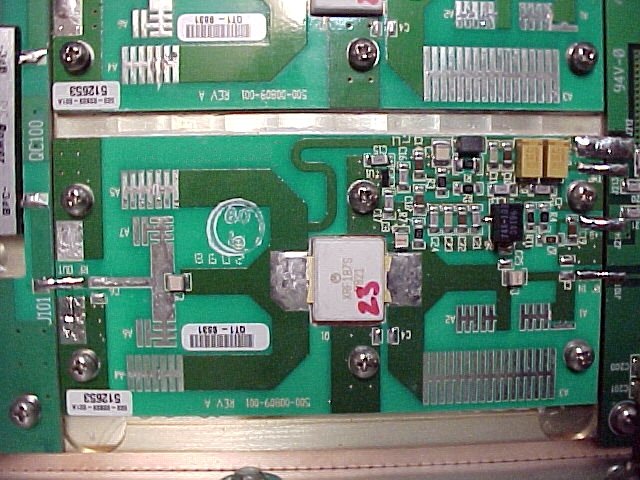
- here is what the original artwork (89k) looks like before modification
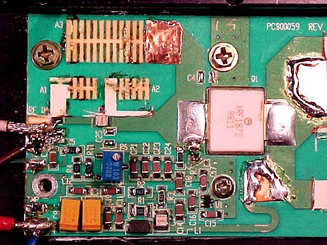
- I modified input circuitry of the XRF187S like this (110k)
- and the output circuitry to look like this (91k)
- an overall view of an individual (73k) amplifier stage after modification
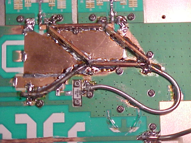
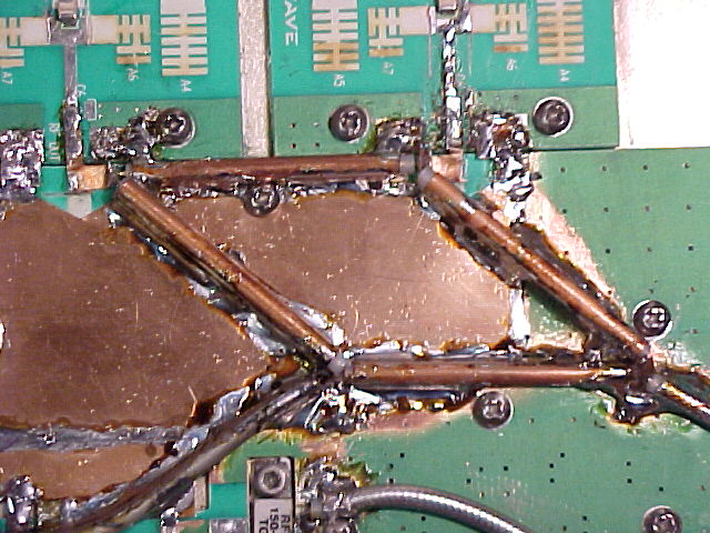
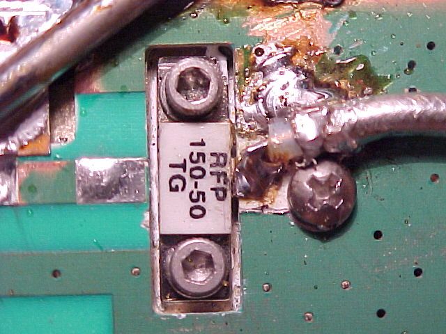
- the output coupler was replaced with a 90 degree 3 dB coupler made from 50 and 75 ohm semi-rigid cable (73k)
- a more closer picture of the semi-rigid coax combiner (88k)
- if you are interested, here (85k) is a similar 3 dB coupler on one of my 1.3 GHz RHCP/LHCP feed horn (87k) experiments
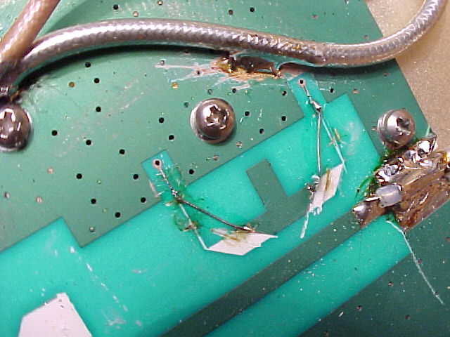
- also the original output power coupler was modified slightly (68k)
- DC output vs. RF power looks like this (8k) now for the dual device amplifier
- the termination was turned around an RF ground modified (74k) to better accomodate the semi-rigid
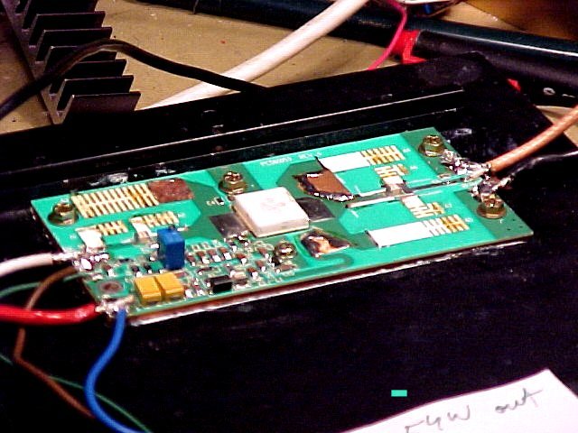
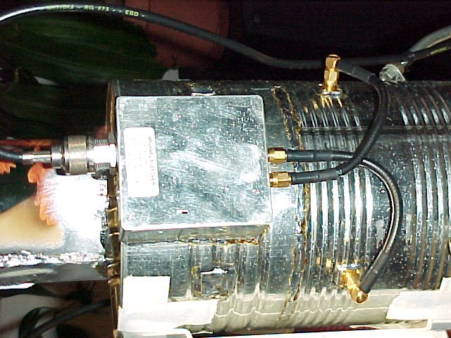
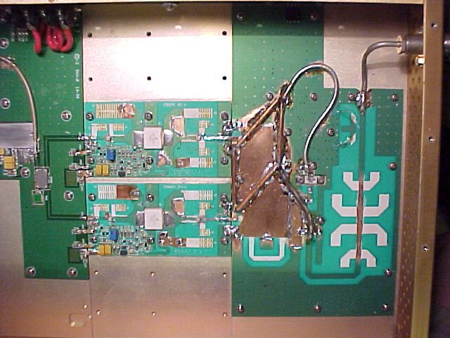
- overall view of two combined (75k) MXRF187S modules at 1.3 GHz
- this dual device amplifier has been working key down 24/7 since June 2002 at 100 W output on our ATV repeater (k)
- the amplifier is being run with plenty of backoff (measured gain plot, 7k)
- drain current for a dual XRF187S stage looks like this (6k)
- the dual XRF187S amplifier can easily supply 170 W PEP, even at Uds = 24 V !
Some figures for a single XRF187S stage:
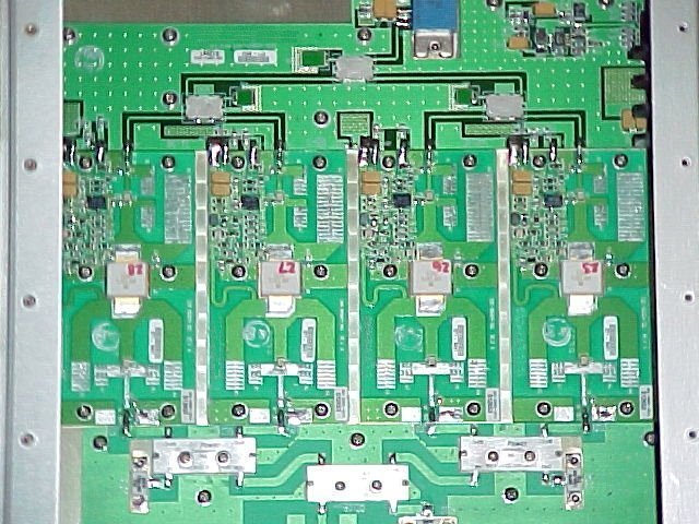
- next to tune up a four * XRF187S (99k) amplifier :-)