Phase I of the Viestikallio SCR-584 pedestal upgrade
The F1EHN/OH2AUE/OH1JJC SCR-584 tracking box
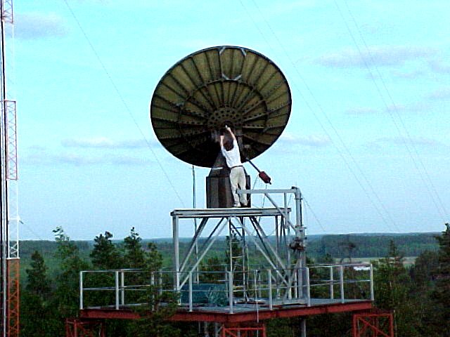
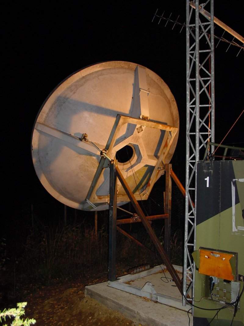
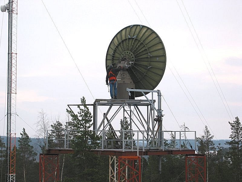
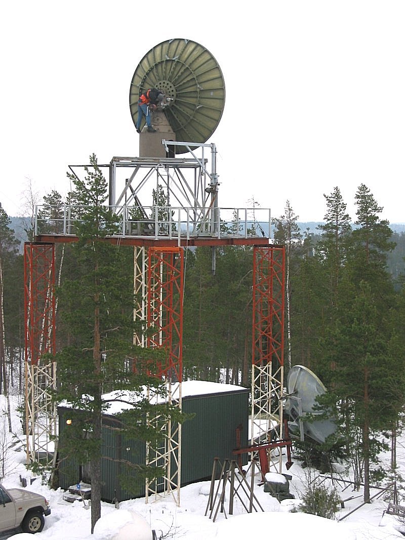
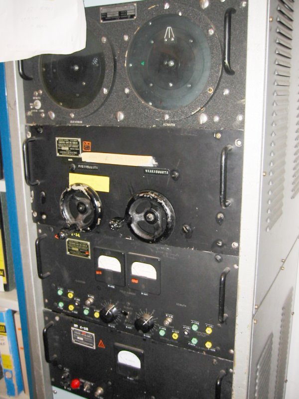
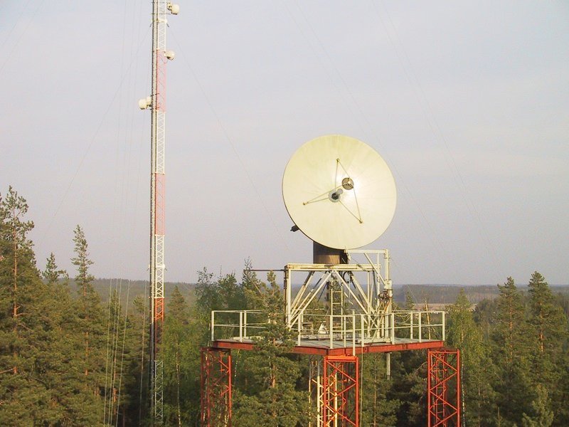
- our OH2Z SCR-584
pedestal mounted 4 meter dish system (62k)
is in dire need of a control upgrade
- this fantastic dish is manufactured in Kuorevesi, serial number
001, surface accuracy +- 2 mm
- originally this was imported into Finland by professor Martti
Tiuri for the HUT Radio Laboratory in
1967
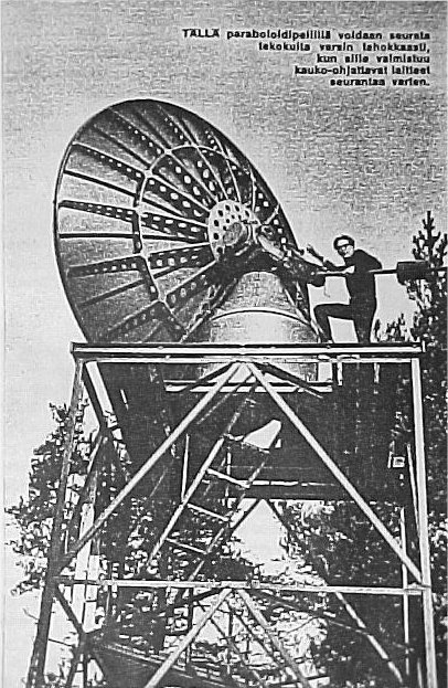
- a photograph of the dish just after installation, Tekniikan Maailma (106k), 8/1967 -
huomaa teksti ;-)
- this dish at OH2Z can be used for Amateur
Radio Astronomy, EME and tropo contacts and also SETI
- the main upgrade, Phase
II, will also be ready for installation soon
- OH1JJC and myself decided to rapidly deploy a temporary F1EHN type
tracking system
- this temporary Phase I upgrade will use the original main axis 60
Hz Selsyns on the SCR-584 pedestal
- these Selsyns will now be excited at 400 Hz to output an accurate
three phase position indication
- D/A conversion to 16 bit resolution is by Data Device Corporation
SDC-501 synchro to digital converters
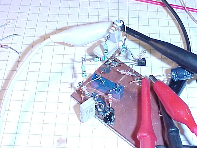
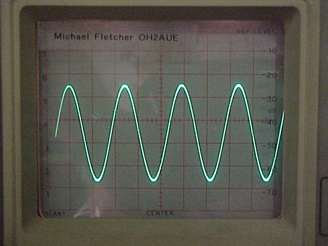
- as the initial 400 Hz source, a very Fletcheresque amplitude
stabilized Wien bridge oscillator prototype
(72k) is used
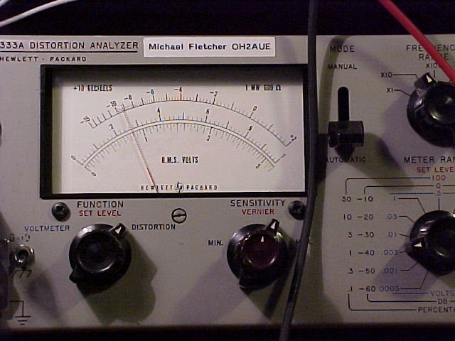
- both azimuth and elevation Selsyns need a 90 V RMS excitation signal (58k)
- this is achieved by amplifying the 400 Hz sine wave with a 5 W
TDA1011 audio amplifier
- feeding a 15 V/230 V toroidan transformer, ample isolated drive is
available with low distortion
- the measured distortion @ 90 V RMS, 400 Hz is < 0.3 % (60k) with even 0.015 % THD
possible at the cost of stability
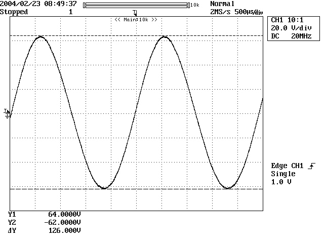
- here is a plot (38k) of the
amplified 400 Hz synchro drive signal (taken with a Yokogawa DL1540L)
- actual antenna motional control is via an F1EHN
interface card using relays
- the upgraded DC motors run off a separate 24 V, 4 A power supply
- are we happy to get rid of the Amplidynes and vacuum valve
amplifier systems !
- a full rack of valve equipment and two Amplidynes can now be
replaced with a 2U high 19" rack unit
- advantages are: silence, low power consumption, less real estate,
less odor and last but not least: computer tracking :-)
- when Phase II is ready to roll, this temporary Phase I unit will
be installed on my 3 m dish (70k)
- this box will now allow antenna tracking of any arbitrary radio
target with ease
- SCR-584 repeatability accuracy is 0.09 degrees, readout resolution
is now 0.01 degrees, accuracy +- 0.02 degrees
- DC motor PWM speed control can easily be added with solid state
FET switching
- 12 V power consumption is 700 mA for the 400 Hz exciter and 1050
mA for the LED display
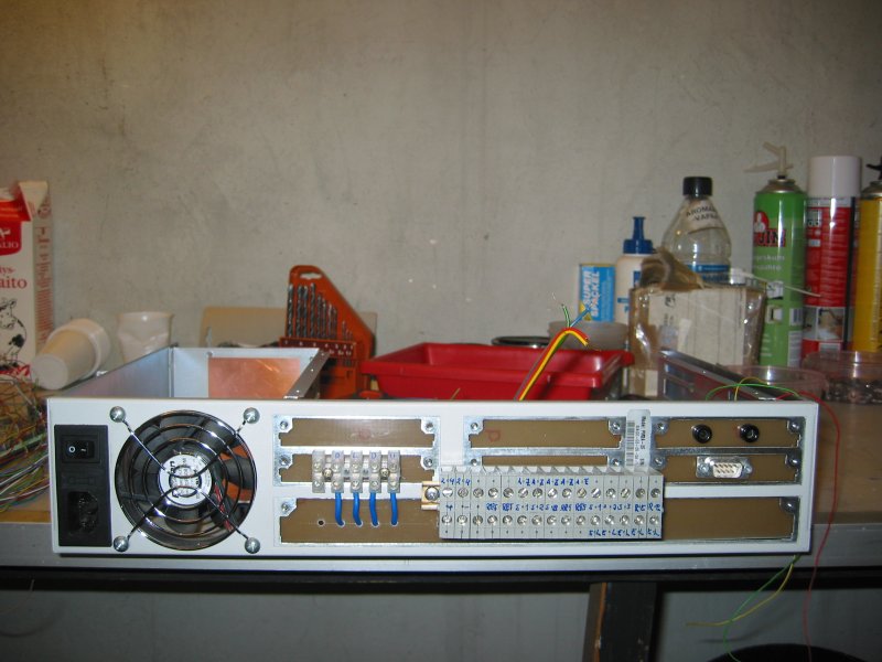
Some photos of the new temporary Phase I controller:
- rear panel view of the temporary Phase I
(76k) trackbox, RS232 computer interface at the right
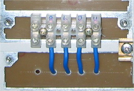
- closeup view of the 24 V DC drive motor
(31k) terminal
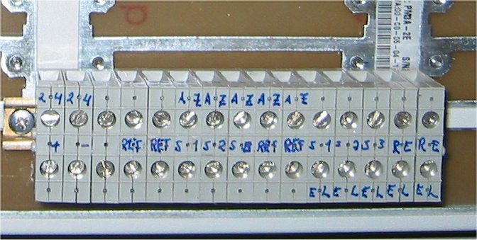
- closeup view of the 24 V feed, 400 Hz excitation and 3 phase
return terminal strip (61k)
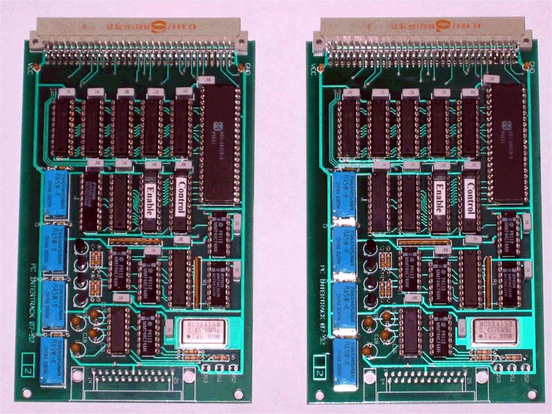
- a couple of equipped and tested F1EHN (79k)
tracking PCB's
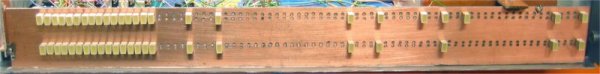
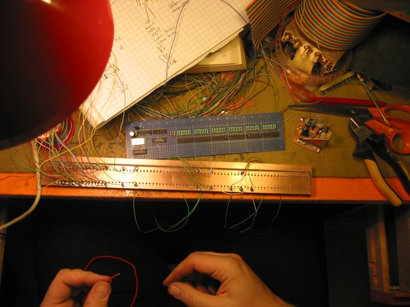
- wiring the ~40 pieces of front panel LED's
(92k) to the drivers
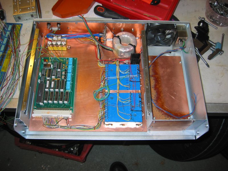
- top overall view of the box (117k)
before completing wiring
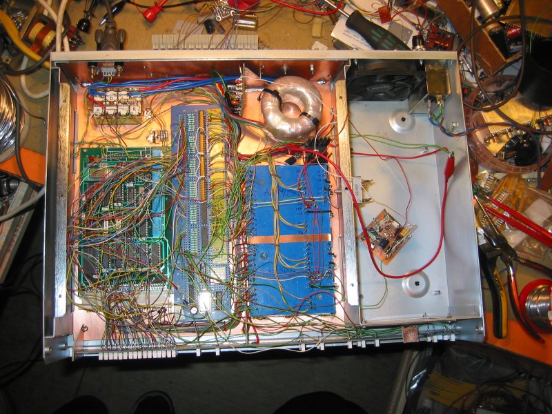
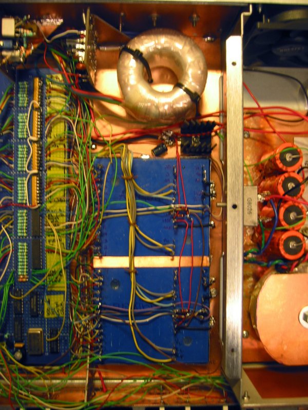
- similar view, but with the CMOS/LED buffer
(150k) board installed
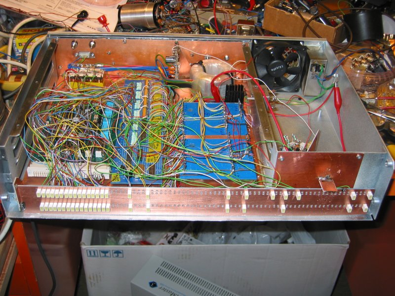
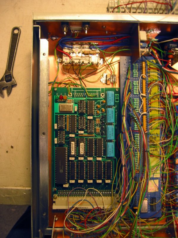
- front inside view of the box with LED
panel (140k) in place
- closer view of F1EHN board wired (129k)
into the tracking box
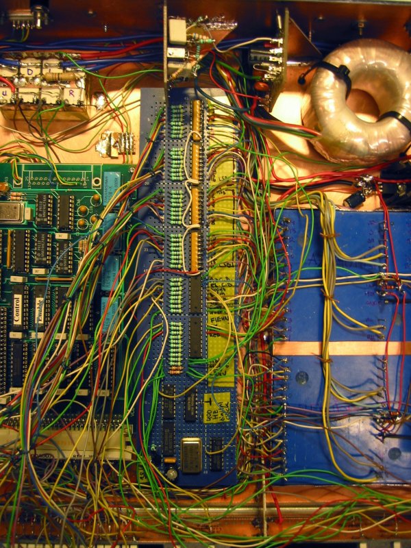
- inside view focusing on the LED buffer
(169k) board
- closeup view of the two DDC synchro-digital
(120k) converters
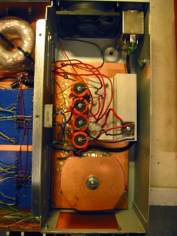
- the 12 V, 2 A continuous, linear regulated power supply (93k)
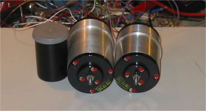
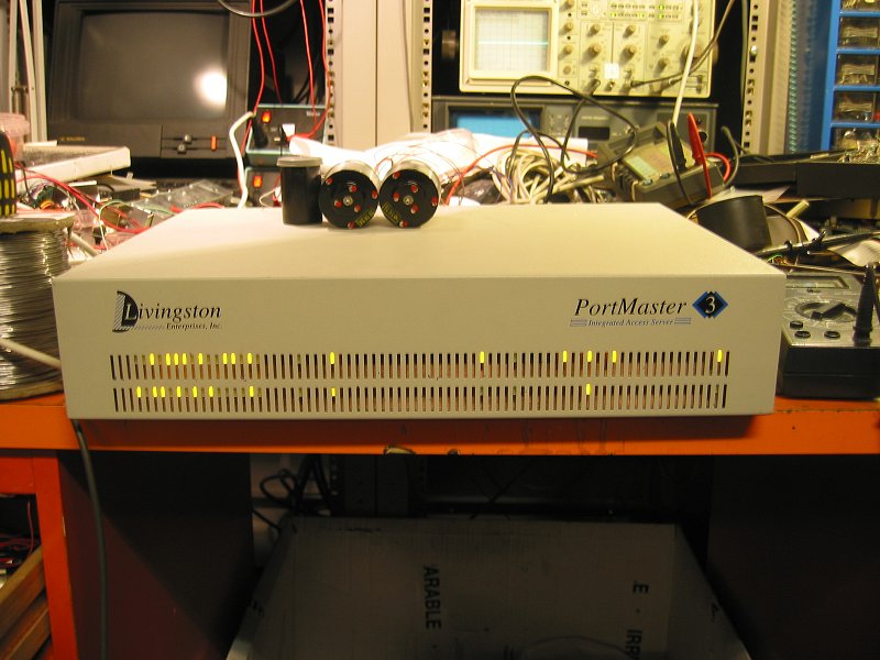
- for testing purposes, two surplus Russian aviation synchros (38k) were used
- and finally a view of the tested (88k)
and almost ready tracking box with cover on (test synchros on top)
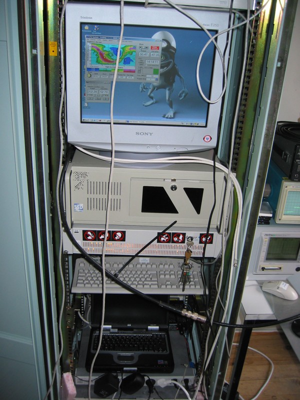
- a screenshot (29k) of
the control PC under live tracking conditions of the OH2Z 4 meter dish
- and another live tracking plot
(30k), hysteresis set to 0.25 degrees (due to torque problems)
- synchros were zeroed to within about 0.2 degrees, final
calibration will be with the software
- it is also evident that the DC motors need a PWM PSU for higher
torque at low RPM
All that is needed for operation is 230 V AC for the box, 24 V for the
motors and a tracking PC !
First installation tests on 21-22.02.2004 weekend (photos OH1JJC
& OH2AUE):
- on Saturday we had really beautiful weather for azimuth synchro (74k) calibration (L->R: OH1JA
& OH1JJC)
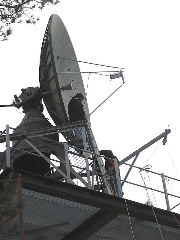
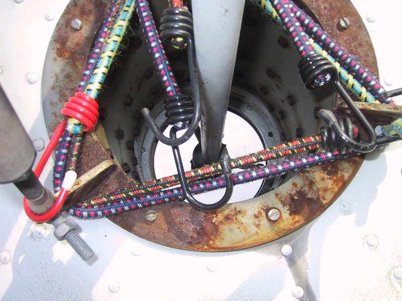
- OH1JJC opening up the service hatch
(90k) to access terminal strips and sychros
- OH1JJC (192k) having another go at
calibrating the elevation synhro (system control radio shack below)
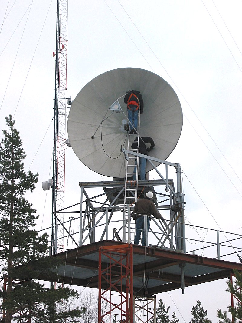
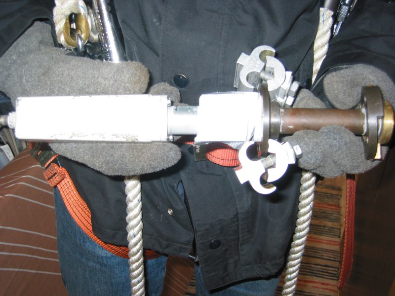
- the negative elevation stop needed shortening (85k), OH2KFH and
OH1JA preparing tools
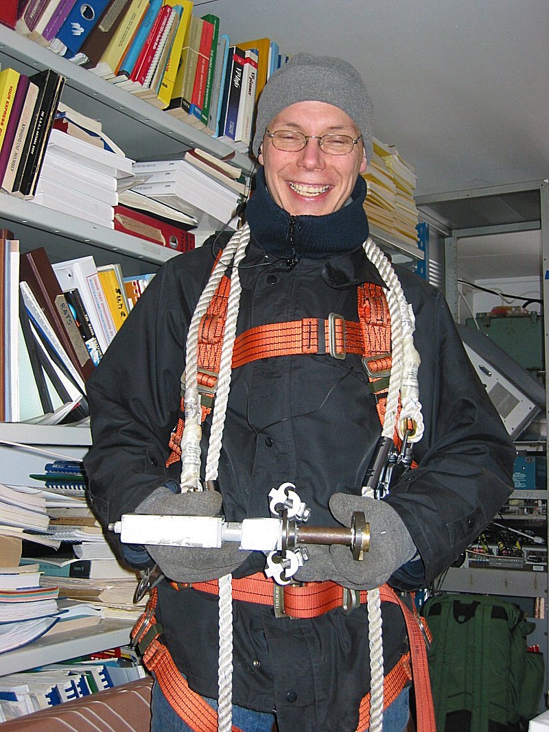
- OH1JA in suitable attire (86k)
for climbing 'Fletcher's Monument'
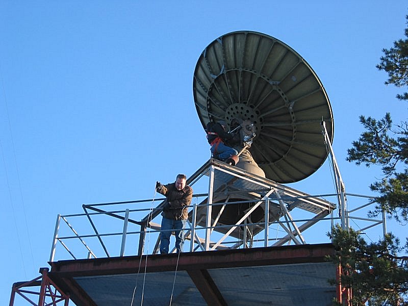
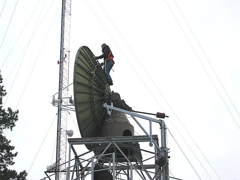
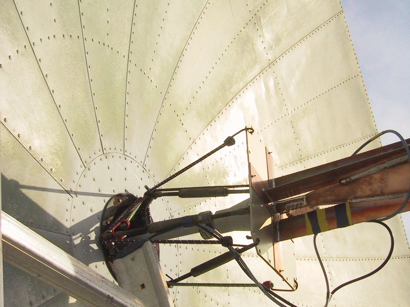
- preparing the plummet line, OH1JJC
(72k) needs to climb on top of the 4 m dish
- amaizingly, the synchros indicate a tilt of less than 0.1 degrees
with OH1JJC (94k) on top of the
dish
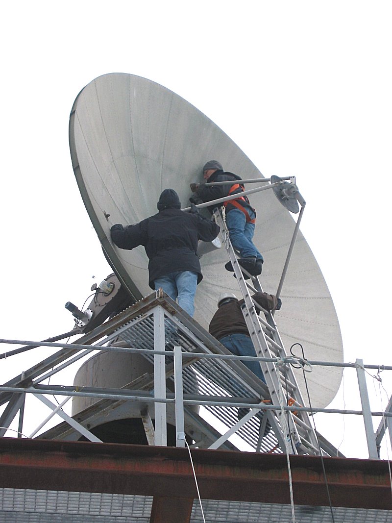
- strapping down the ladder
(77k) for accessing the feed tripod (L->R: OH2JMS, OH1JJC)
- next, the 2.4 GHz
tropo feed (192k) is removed (T->B: OH1JJC, OH2JMS, OH1JA)
- after removal of the 2.4 GHz feed, the X band Cassegrain
(127k) feed goes on (L->R: OH2JMS, OH1JJC, OH1JA)
- poor fellow cannot (240k)
believe, what he is taking up next... (OH1JJC)
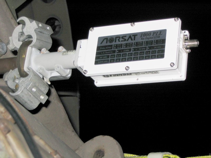
- a very ad hoc Ku band
converter (88k) hashed onto the circular waveguide adapter with
grounding joints
- equally quickly put together radiometer (105k) for sun
noise measurements (modified TV-sat RX above tracking box)
- work to continue with subreflector and feedhorn alignment
calibration
Second installation tests on 05-07.03.2004 weekend(photos by OH2KFH
& OH2KFX):
X band receiver lab work during 16.04 - 18.04.2004 (photos by
OH1JJC & OH2AUE):
- here is the block diagram (38k) of the
8.4 GHz DSN band receiver
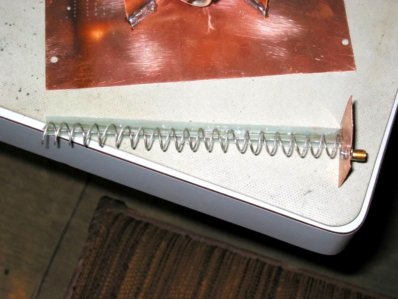
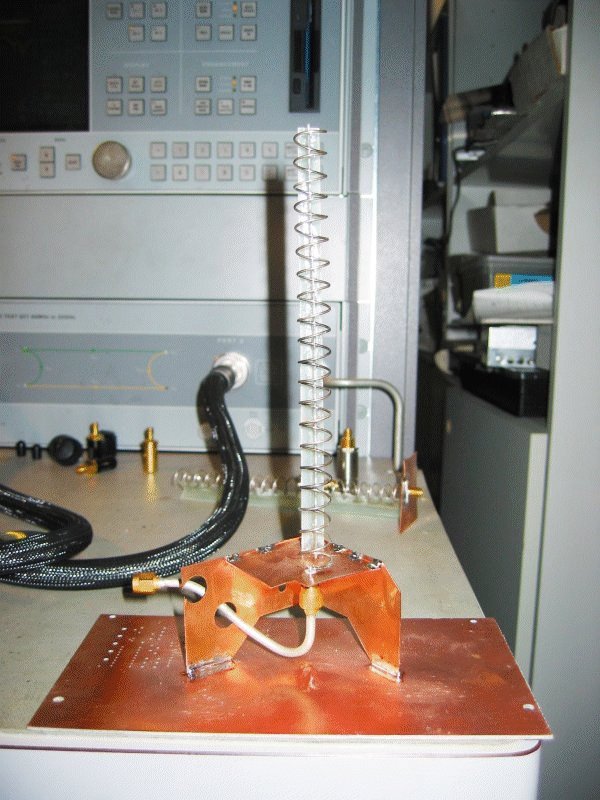
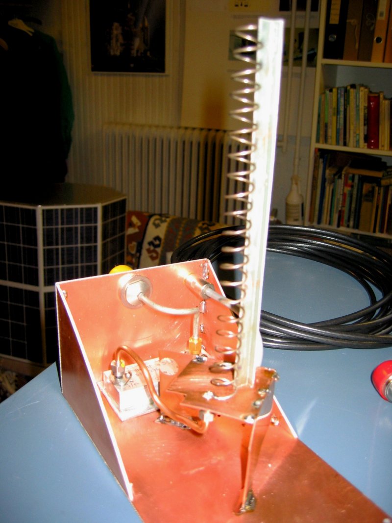
- the first produced radiator was a 20 turn 8.4 GHz LHCP helix (83k)
- and to match it, a 20 turn RHCP
helix (99k), also for 8.4 GHz
- here to be seen with the 8.4
GHz LNA (118k) integrated to it
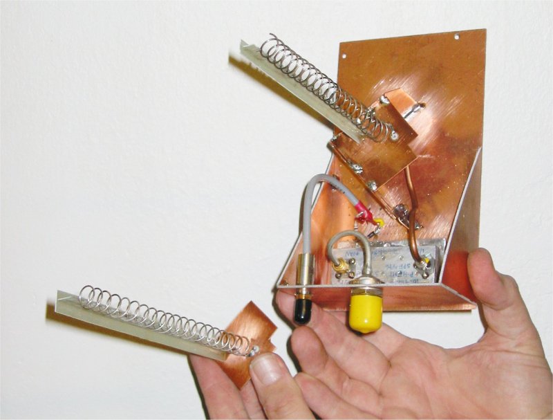
- a view of both helices
(66k), pretty small, eh ?
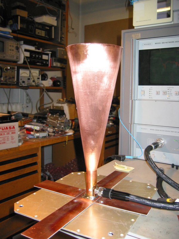
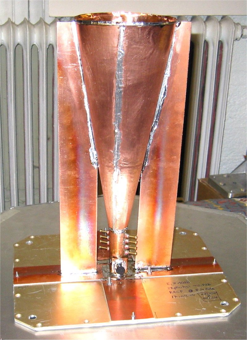
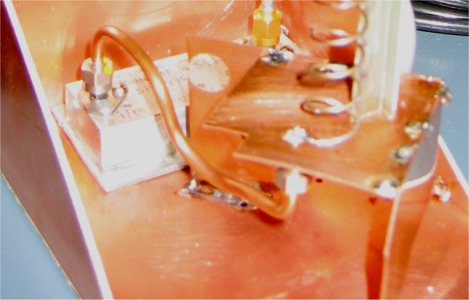
- also an RHCP horn (91k) was
manufactured for lower sidelobes
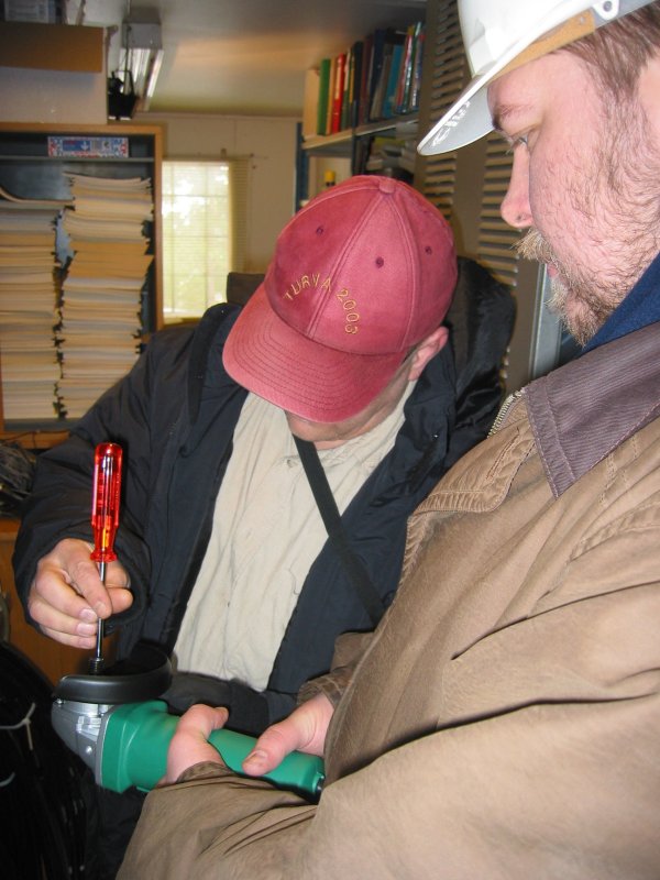
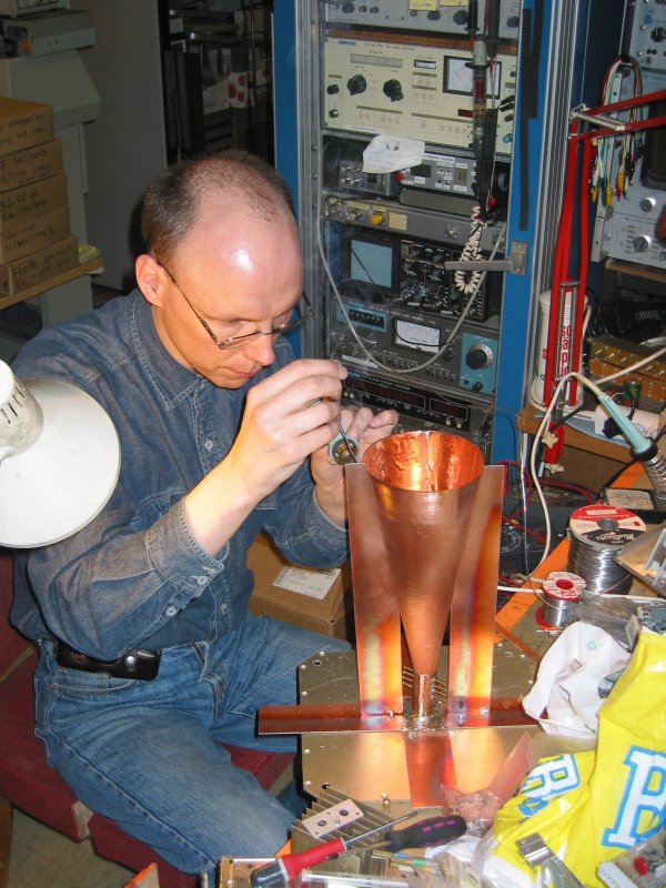
- after verifying linear polarisation performance, an RHCP polariser (118k) was implemented
using a set of eight screws (OH1JJC at the bench)
- due to limited waveguide (also made from copper foil) real
estate, producing a decent PTFE polariser proved too difficult for the
time given
- a photo of the RHCP feed horn
(168k) donning the polariser (ellipticity measured less than 0.8
dB)
- using the RHCP and LHCP helices, the cross polarisation isolation
was determined to be approx. 17 dB
- matching is not ideal (did not implement matching screws due to
space constraints) but then, neither is the LNA input matching either
:-)
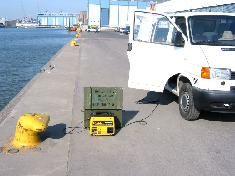
- on Sunday, the weather was perfect for field testing (89k), albeit
in the city way, down by the Helsinki city docks
- a view of the RF test
setup (82k) for evaluating feed system Thot/Tcold using cold sky
vs. ground (ambient ~288 K)
- empirically searching for best line
length (77k) in situ, found this barrel to give best Thot/Tcold
- for the RHCP helix, this line
(78k) length gave best Thot/Tcold for cold sky vs. ground (288 K)
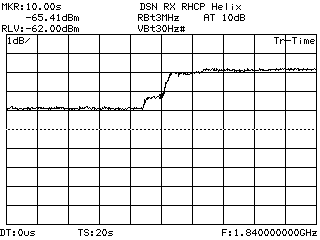
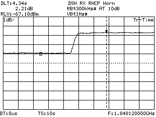
- for the LNA and RHCP helix combination, the hot/cold difference (10k) was
optimised to approx. 2.1 dB
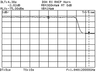
- the optimised LNA/RCHP horn combination gave ~2.8 dB (10k) for the hot/cold
difference
- jusf for interest, here is the hot/cold result for the LNA/horn
combination using a 0.17 dB loss (10k)
piece of coax
- worst results for Thot/Tcold were around 1 dB with
cable/adapters that exhibited losses of just a few tenths of a dB
- and finally, a plot of a OH1JJC
(10k) walking past the sky pointed horn at a distance of about 2 m
- the man is proven to be of the radiating sort :-)
- the event was televised by OH2KO/mobile over the Helsinki City
ATV repeater, OH2RTE
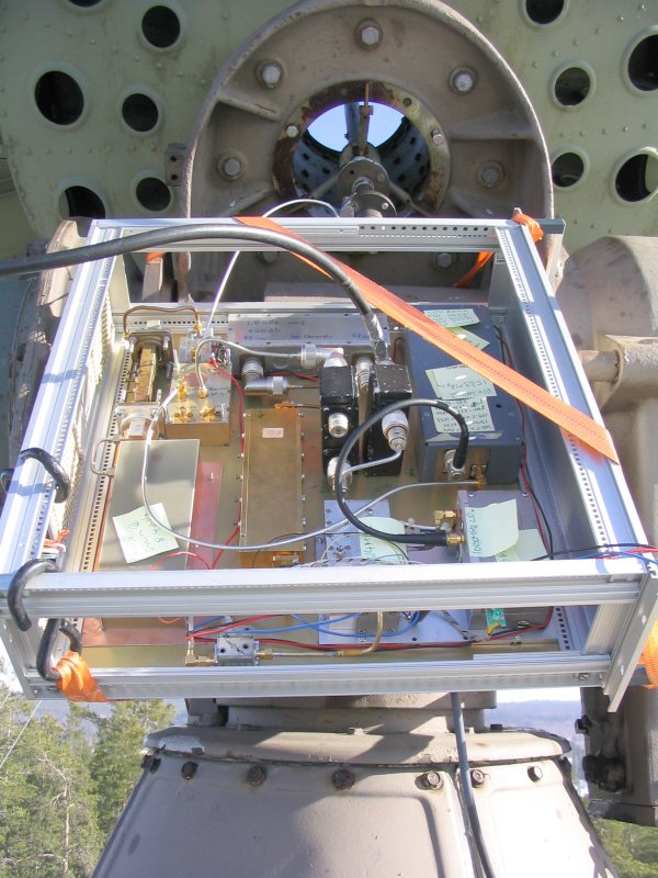
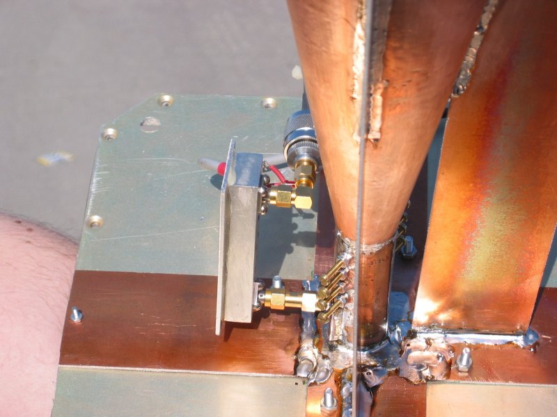
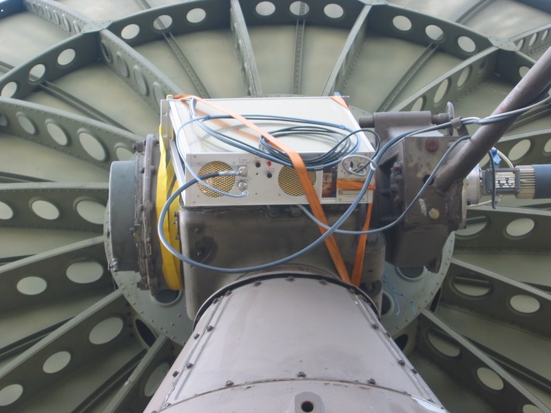
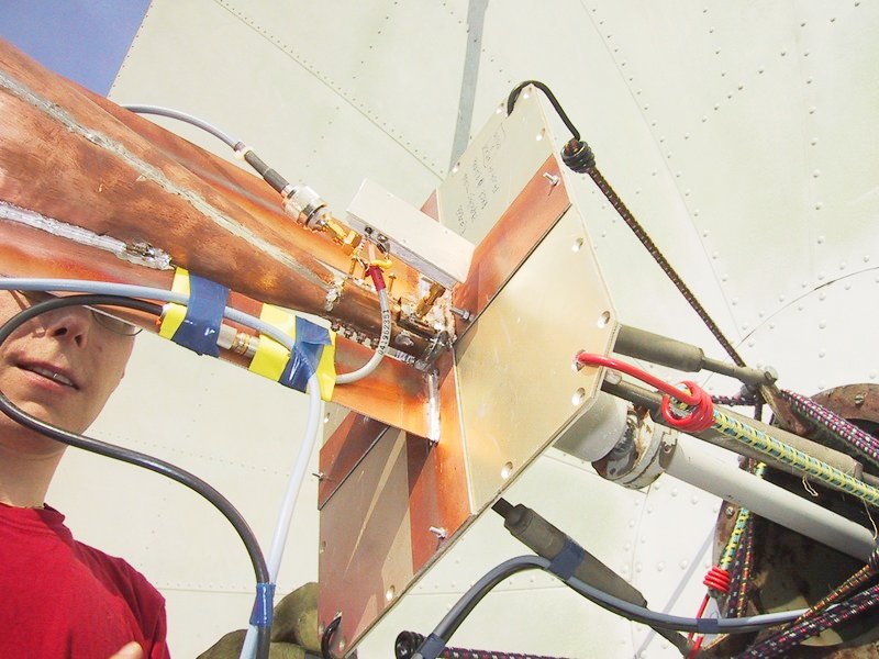
- for this very first on-air test of the 8.4 GHz system, the receiver (98k) was mounted as
before
- the newly designed feedhorn and noise matched LNA were installed (103k) using
automobile rubber ties
- here is a closer
(130k) view of the packing ties holding down the horn assembly
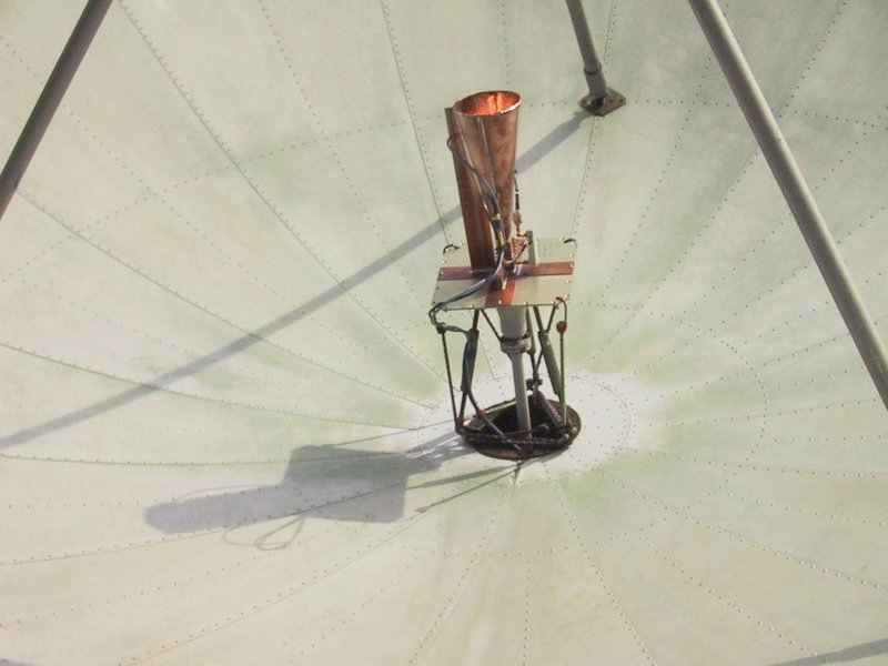
- the feedhorn being centralized empirically (99k) by
OH1JJC
- and a view of the feedhorn assembly final installation (68k) -
for this session :-)
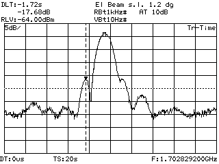
- many times the good old sun
(87k) was used for a quick check for overall approximate
performance of the 8.4 GHz receiver
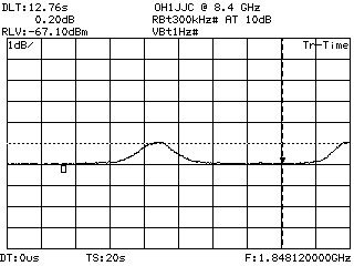
- after feeding in the Right Ascension and Declination for Rosetta
and also calibrating feed offsets, the tracking system (130k) kept us
on beam
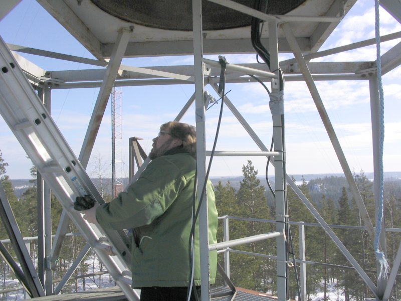
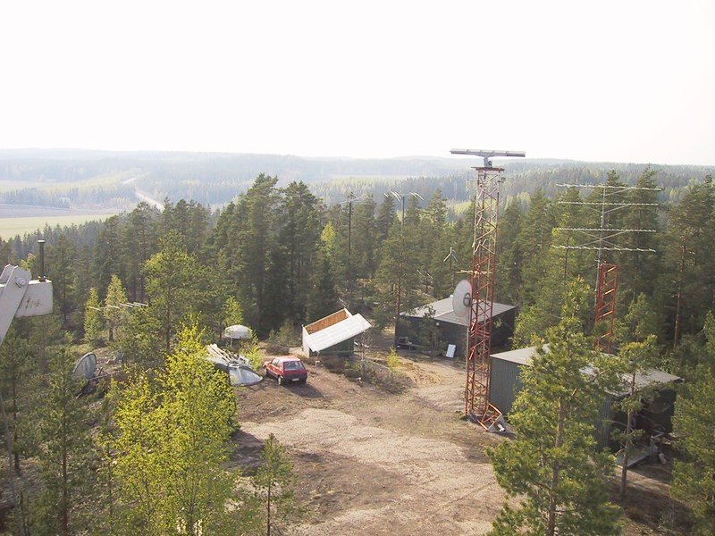
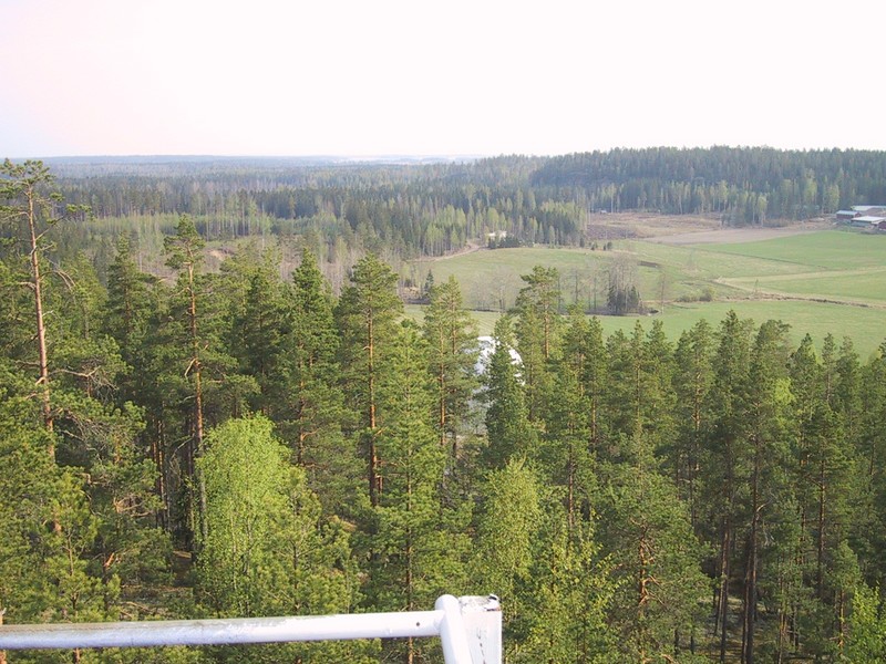
- as always, the view from on top of the 'Monument' (122k),
as it is known, is quite spectacular
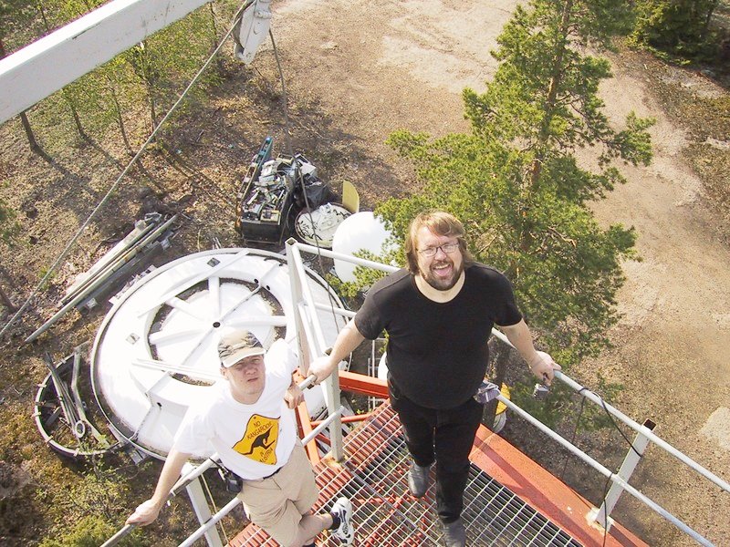
- OH3HDK and myself checking out the feedhorn assembly (194k)
with our 5.5 m dish project visible on the ground
- another horizon view, this time with the URSA telescope (168k) building
visible behind the forest
- during the Thursday reception session, activities were webcasted
over our WebCam (26k) and audio
stream onto the internet
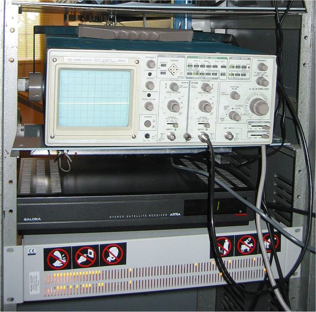
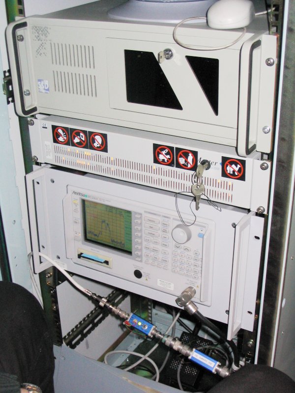
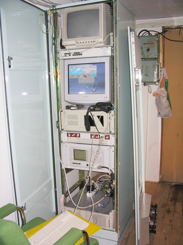
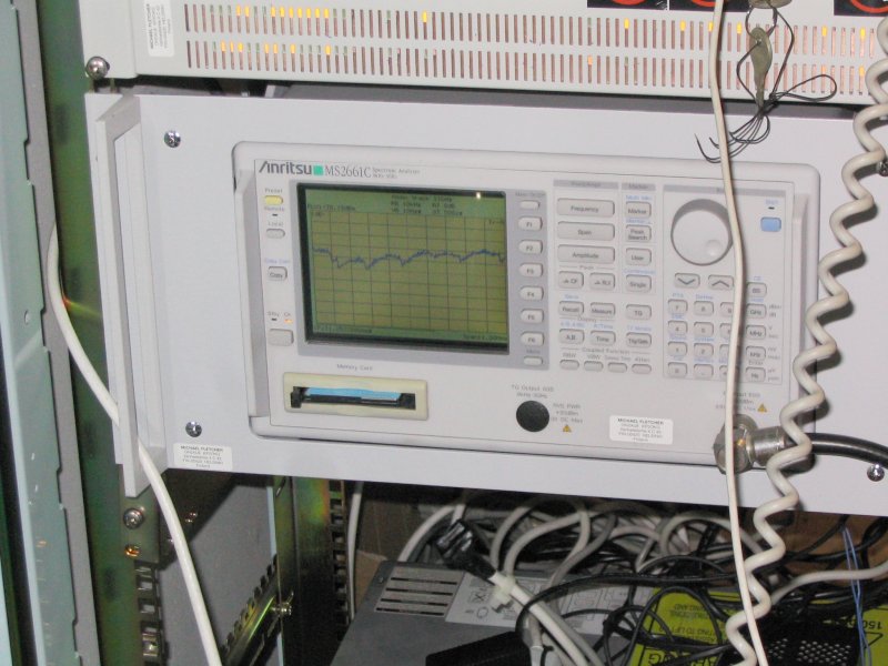
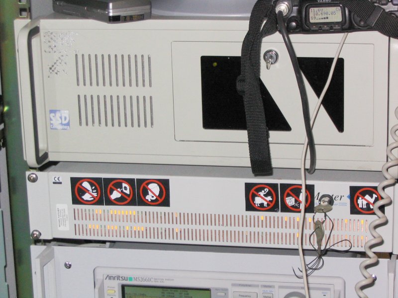
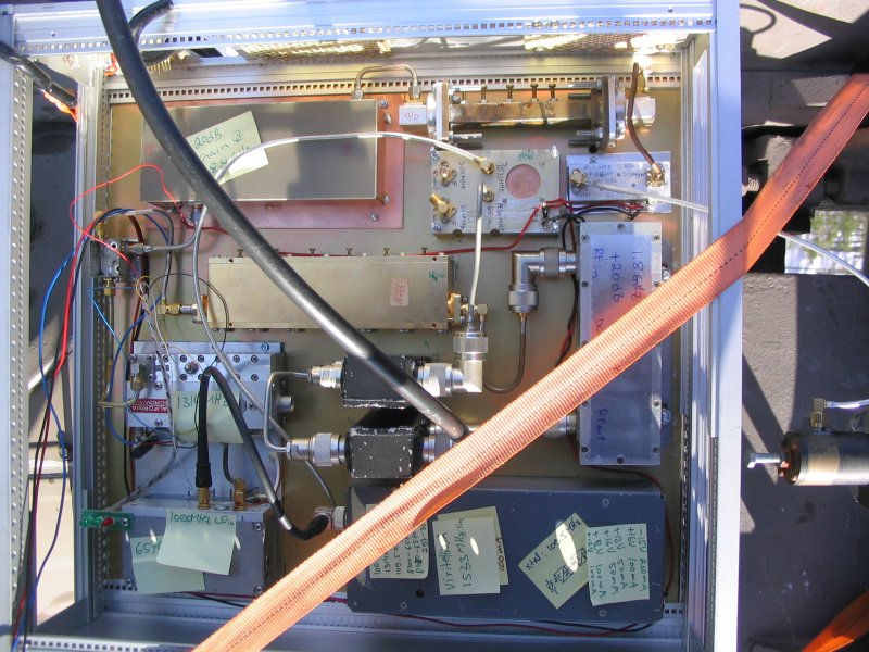
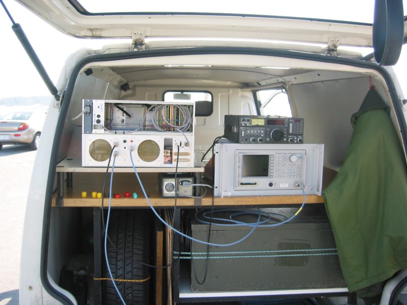
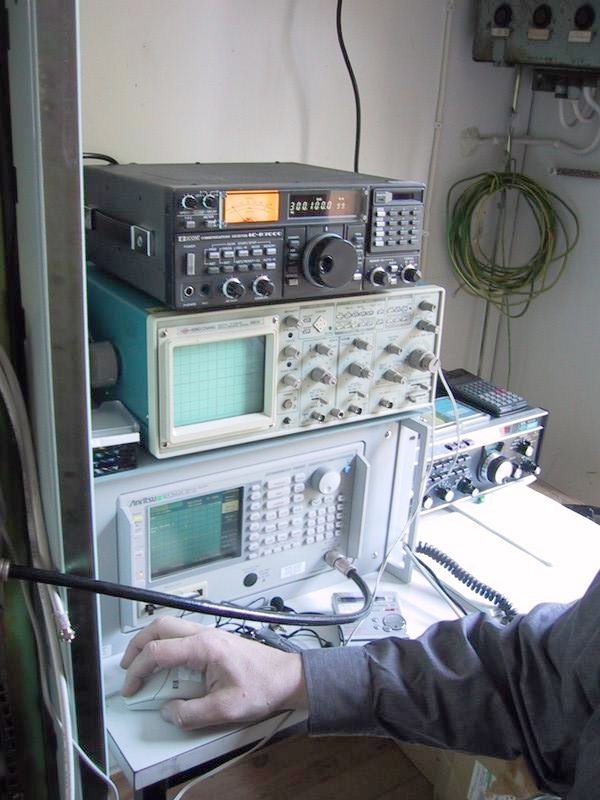
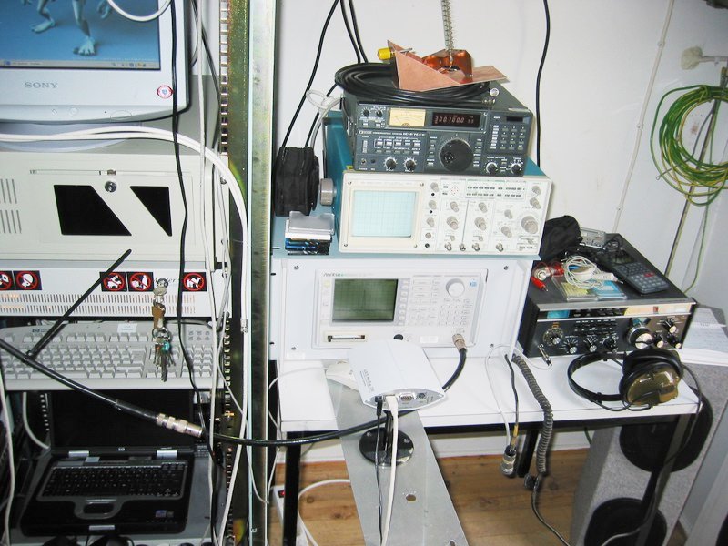
- a photo from inside the radio shack with the DSN receiving system (81k) back
end (IC-R7000, Drake R7A, Anritsu
MS2661C and Hung Chang HC8604)
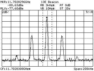
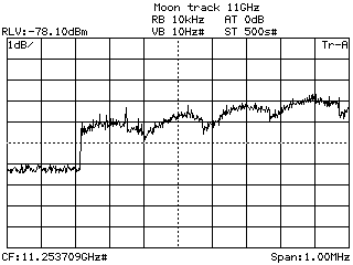
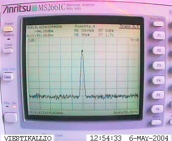
- here is a corrected spectrum analyser plot (13k) of the Rosetta
carrier at approx. 42 dB/Hz C+N/N
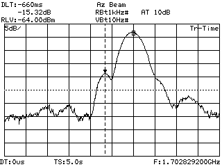
- this is an audio spectrum
plot (72k) of the detected audio (100 Hz sidebands from Drake R7A
receiver PSU)
- here is an audio file of the Rosetta CW carrier (206k) on 8421.619 MHz at
the time of reception (compressed, 8 kHz sampling, 8 bit resolution)
- this is a similar audio file, but with less postprosessing compression (1.1M),
22 kHz sampling, 16 bit resolution
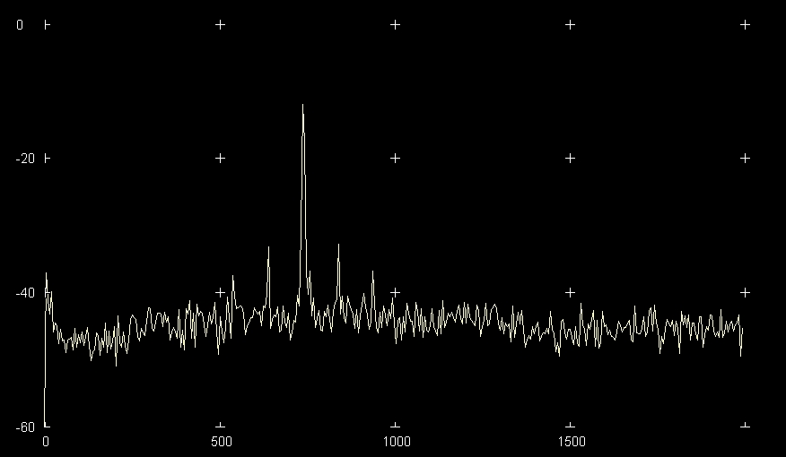
- and here is a 700 - 800 Hz spectrogram
(130k) of the Rosetta signal (drift from thermally totally
unprotected receiver being exposed to the elements)
- for more photos, please check out Hämy's web
archives
- and more photos
by Matti, OH1JJC
- many thanks to Hämy, OH4KPN & Matti, OH1JJC, whom
rapidly arranged streaming audio and WebCam (113k) coverage for
this event :-)
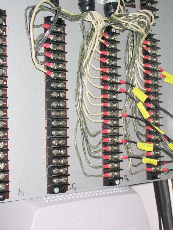
Miscellaneous documents:
- SCR-584 control cabinet terminal block connections as of 15.01.2005 (outside view)
Updated 13.01.2017